What You Need
For the Relay version of the circuit (which turns the arcade cabinet on and off)
1 x Parallel Printer Cable
3 x LEDs (pref. different colours)
3 x 220ohm Resistors
1 x 1.8K Resistor
1 x 20K Resistor
1 x 100nf (0.1 uf) capacitor
1 x Diode (1N4001)
1 x BC237 Transistor
1 x 4510 (BCD Up/Down Counter)
1 x 7404 (Hex Inverter)
1 x 14pin DIL IC Sockets
1 x 16pin DIL IC Sockets
2 x Double Throw Switches (for testing)
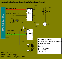
The circuit diagram is as follows:-
(Click for a larger version)

For the 4066 switch version of the circuit (the safer option - simply cuts the signals to the monitor)
1 x Parallel Printer Cable
3 x LEDs (pref. different colours)
3 x 220ohm Resistors
1 x 20K Resistor
1 x 100nf (0.1 uf) capacitor
1 x 4066 (Quad Bilateral Switch)
1 x 4510 (BCD Up/Down Counter)
1 x 7404 (Hex Inverter)
2 x 14pin DIL IC Sockets
1 x 16pin DIL IC Sockets
2 x Double Throw Switches (for testing)
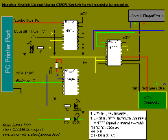
The circuit diagram is as follows:-
(Click for a larger version)

Note: When you buy the printer cable make sure that the plugs are screwed together rather than sealed. This make identifying which wire goes to which pin a lot easier - as you can just open it up and look. Also, you can by a 25pin Serial Cable instead if you wish (it's what I bought for this project).
They're cheaper and have significantly less wires so are easier to work with. HOWEVER , not all the pins we need will be connected - so you will need to rewire the socket for this project.
To use your cable in this project, simply cut the cable (leaving a good length attached to the male socket) then open up the socket and identify the wires you need:-
'Strobe' (pin 1)
'Data bit 7' (pin 9)
'Acknowledge' (pin 10)
'Busy' (pin 11)
'Ground' (pin 25)