What follows are descriptions and pinouts of ICs used in the projects on this site.
|
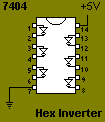
7404 : Hex Inverter
Used In: PC2JAMMA Project, Saturn Mod Notes: This chip contains 6 independent 'inverters'. The '74' series of chips is a large family of ,originally, TTL (Transistor to Transistor Logic) ICs. The chips are identified by the number '74' then one or more letters then a number to indicate the function of the chip i.e. 74L04 , 74LS04 |
the 74HC04 (or 74HCT04) for the PC2JAMMA Project
and the TTL version (74LS04) for the Saturn Mod
The CMOS versions have a lower power consumption, don't require decoupling capacitors and are more stable over a range of temperature and power supply fluctuations.
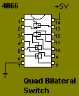
4066 : Quad Bilateral Switch
Used In: PC2JAMMA Project
Notes: This CMOS chip contains 4 independently controllable switches. When closed, each switch has a resistance of about 100ohm
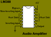
LM380 : Audio Amplifier
Used In: PC2JAMMA Project ,Saturn2JAMMA Project, Playstation2JAMMA Project SNES2JAMMA Project, Master System2JAMMA Project
Notes: At least one of the heat sink pins (3,4,5,10,11,12) must be connected to ground, also a decoupling capacitor must be used.
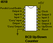
4510 : BCD Up/Down Counter
Used In: PC2JAMMA Project
Notes: This CMOS counter is used as a 'latch register' rather than a counter in the PC2JAMMA Project. 'Carry In' (pin 5) uses inverse logic, high ('1' or +5V) for inactive , low ('0' or 0V , Ground) for active
Notes on Handling CMOS chips
CMOS chips (for our purposes - 74HC04,74HCT04,4066 and 4510) are susceptible to damage from electrostatic voltage; to combat this IC manufacturers build protection circuits into the chips. Typically, this will protect the chip for voltages up to between 800V and 4kV (depending on the chip).
However, it's possible to pick up a charge of around 10kV by simply walking across a nylon carpet.
The correct way to work with CMOS chips is to use an earthed bench, a grounding wrist strap, a soldering iron with a ceramic shaft etc.
To be honest - I use none of the above and have not ruined a CMOS chip yet. Just try to take a few simple precautions :-
(i)Try to do your soldering in a non-carpeted area
(ii)Use IC sockets rather than soldering the ICs directly onto stripboard. This way your soldering iron never comes into contact with the CMOS chips.
(iii)Handle the chips as little as possible, and avoid holding them by the legs (whenever possible).