
Country Circuit
Time to make the circuit, it's very simple just 2 resistors and a 7404 (hex inverter).
The circuit diagram is a follows
Here's a quick explanation of what
it's doing.
The two ouput lines from the switch are held 'low' (i.e.
at logic 0) by the 2 resistors until they are connected
to +5V by the swithc.
The output for the JP10/11 pair is the inverse (1 for 0,
0 for 1) of the output for JP6/7. This configuration
gives Japanese for the top switch setting, American when
in it's centre off position and European in the bottow
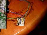
switch setting. The completed board should
look something like this

Now you need power for your circuit, you take this from
the Saturn's board. Again with the board upside down and
the joypad ports pointing to your right, look at the top
right hand corner of the board. You'll see 5 large
soldered pins, this is where the powersupply connects to
the Saturn board.
From left to right, the pins are +12V, +5.2V, +5.2V ,
Ground , Ground
We need +5.2V and Ground, so solder a wire onto the
second pin from the left , and another wire onto the last
pin on the right.

You'll notice I've soldered 2 lines onto the +5.2V pin,
this is because you'll also a +5.2V for
the 50/60Hz switch later on.
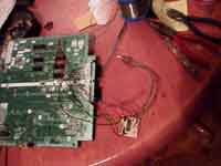
The complete country circuit including power should look
something like this
