
Good news and bad news.
The good news is that the 50/60 switch is just that - a switch with no electronics whatsoever.
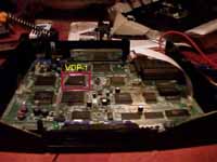
The bad news is it's a little bit more messy than the country mod. Basically, the vertical refresh rate/picture size of the Saturn is determined by the logic value at pin 79 of the VDP-1 chip. If it's 0 (ground) the Saturn runs at 50Hz, if it's 1 (+5.2V) the Saturn runs at 60Hz.
with one of these - 315-5964 , 315-5690 , 315-5890)
so the most reliable way of identifying it is by it's leg count -
it's the only 160 leg chip on the Saturn board.(Don't worry, you
don't have to count the legs, the number of legs are marked on the board), it should also be marked 'IC14'.
If you turn the board the correct way up, with the joypad ports
facing you - it'll be near the far left hand corner of the board;
probably just below the word 'SEGA' on the board.

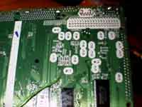
You'll see that the trace from pin 79 loops away to the left of the chip, then goes to the underside of the board through a hole.
Turn the board over and locate this hole.
The trace continues up to a set of jumpers marked JP1/JP2, so it may be easier to trace this back to find the starting point.
Once you're definite you've located
the correct hole, take some wire, strip it and cut all
but a few (1 to 3) strands of copper form the exposed bit
of wire. Then solder this onto the small hole.

Now you need to cut the trace BEFORE it branches of
anywhere else (i.e. before any other holes in the board).
I use a small jeweller's screw driver and basically
'scratch' the trace off just above where the wire is
soldered. Be very careful not to accidentally remove
other traces on the board.
I also suggest you put a bit of PVC tape across the wire,
to relieve any stress on the solder joint - as it may not
be mechanincally strong.
Now ,take the other end of that wire and solder it onto
the centre pin of a DT (double throw) switch.
Then solder one of the outside pins to +5.2V and the
other outside pin to Ground (taken from the pins shown in
the country code section).
![]()